Electronic Kit for Amateur Radio Operator & Home Brewer from Korea(HL5FTC & DS5TUK)
2. Digital Frequency Display Module
6. Adjustment without measurement device
EHB-1 Assembly Guide 3. TRX Board
TRX Board will use a lot of the parts. Then I find, the location of components is very difficult. Locate the parts you need to insert still in place to properly do the normal operation, is forced to traverse the gateway. Pdf files below, the location of each part was well placed to clean up. IlHo Kook (6K2HJI) is created by the file. For other people, so please see the file made.
![]() English/TX & RX/EHB-1/Guide/3. TRX Board/ASSEMBLY.pdf
English/TX & RX/EHB-1/Guide/3. TRX Board/ASSEMBLY.pdf
Directional components, will be inserted with caution. TR /
Diode / IC / electrolytic capacitor is a component in the direction. If you do
not have the correct orientation of these parts will be damaged or malfunction.
When you insert parts, insert, making sure, please check again.
Crystal filter used in the four crystals, with reference to the photo below,
please connect to ground the body. This is done via wire cut parts.
The point at which the need for external wiring, Pin Header used. Short the pins
facing up, insert a long pin is facing down. After soldering, cut the side right
will hold the remaining pins.
The following is the creation of a matching transformer.
The beads used for matching transformers, Bourns Corp. in the United States for
the Ferrite Bead EMI Filter is shown.
For further information please refer to the data sheet below.
![]() English/TX &
RX/EHB-1/Guide/3. TRX Board/fb_series TRANS CORE Datasheet.pdf
English/TX &
RX/EHB-1/Guide/3. TRX Board/fb_series TRANS CORE Datasheet.pdf
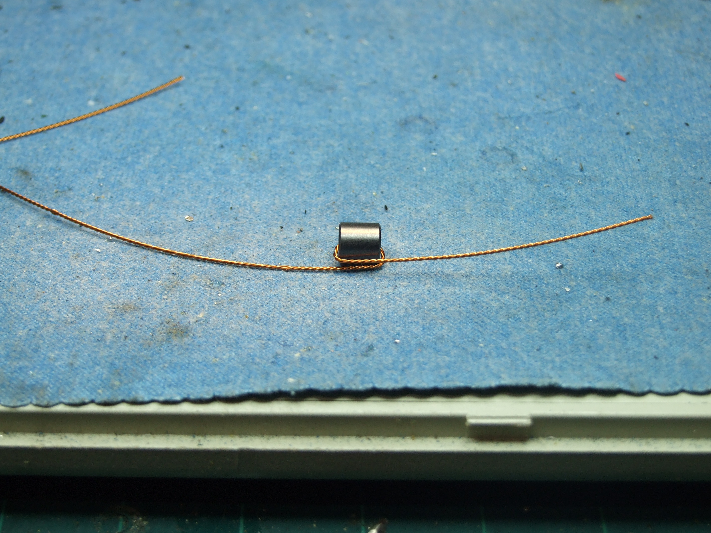
Prepare the first bead and coil. 3-strand twisted coil, is
five times when you close.
Coil pre-bite crossed electric drill, cut by about 15 centimeters long I've
Enclosure.
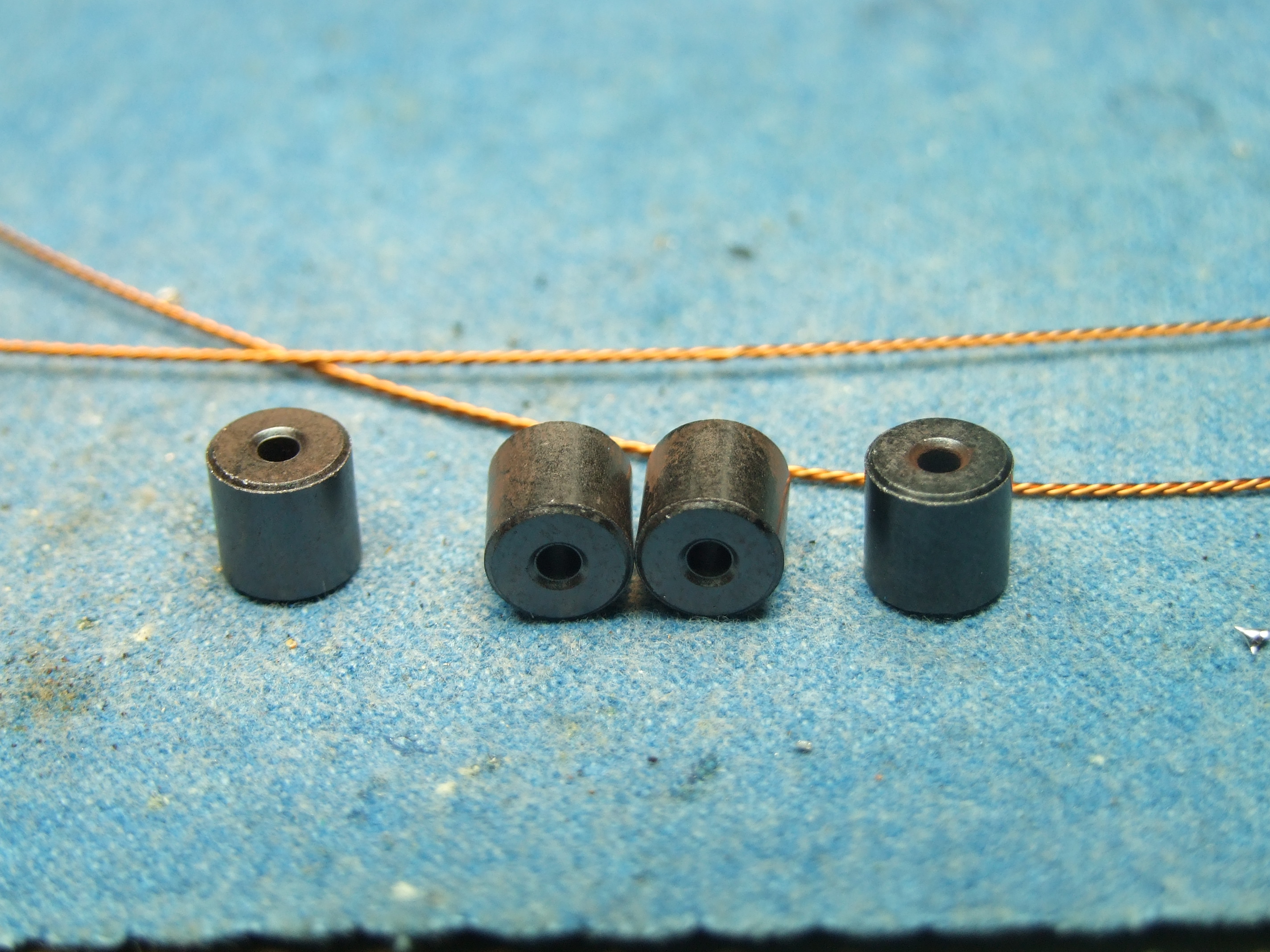
Beads (core) and the appearance of the coil is in the photo below.
Closer inspection of the core hole as a magnifying glass, the edges are quite
sharp. If the coil winding of sharp edges, peeling off the enamel on the coil,
is a short circuit, will not let the role of matching transformers.
So first, in the form of diamond-pointed tool, turn the corner to put the holes
on the core softens a little. Gently make holes are the opposite.
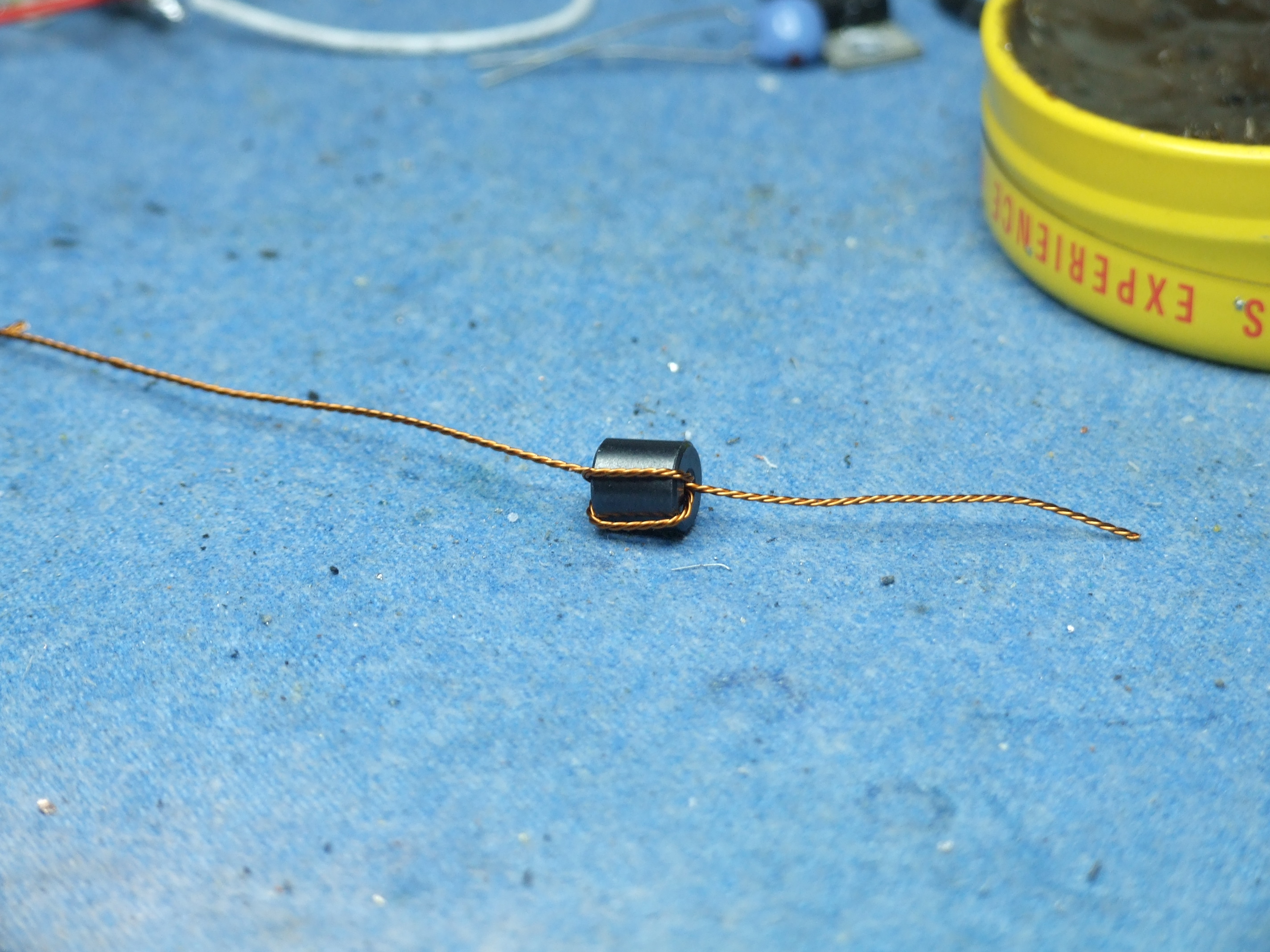
The coil very tightly kinked as shown in the photo below.
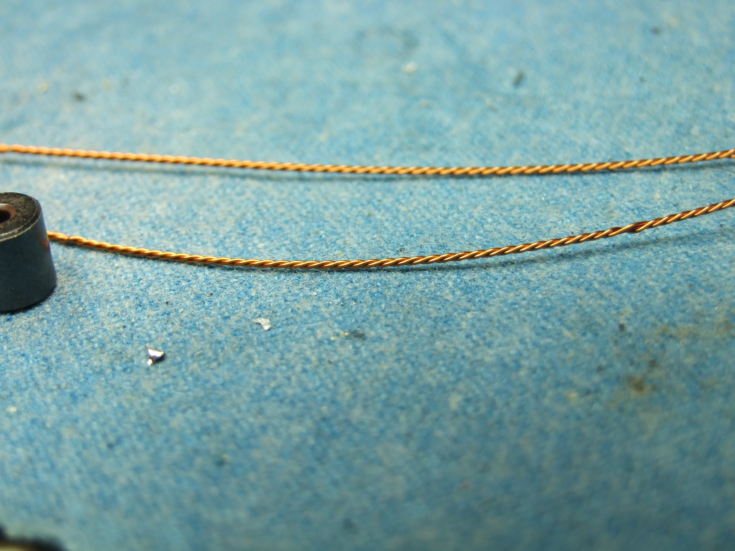
Reminds of the core hole will pass through the coil. This is one sense. We need to wrap the matching transformer to 5 times, 5 times to loosen the coil winding will not be passed. Therefore, small size, but tightly, tightly wound is'll need.
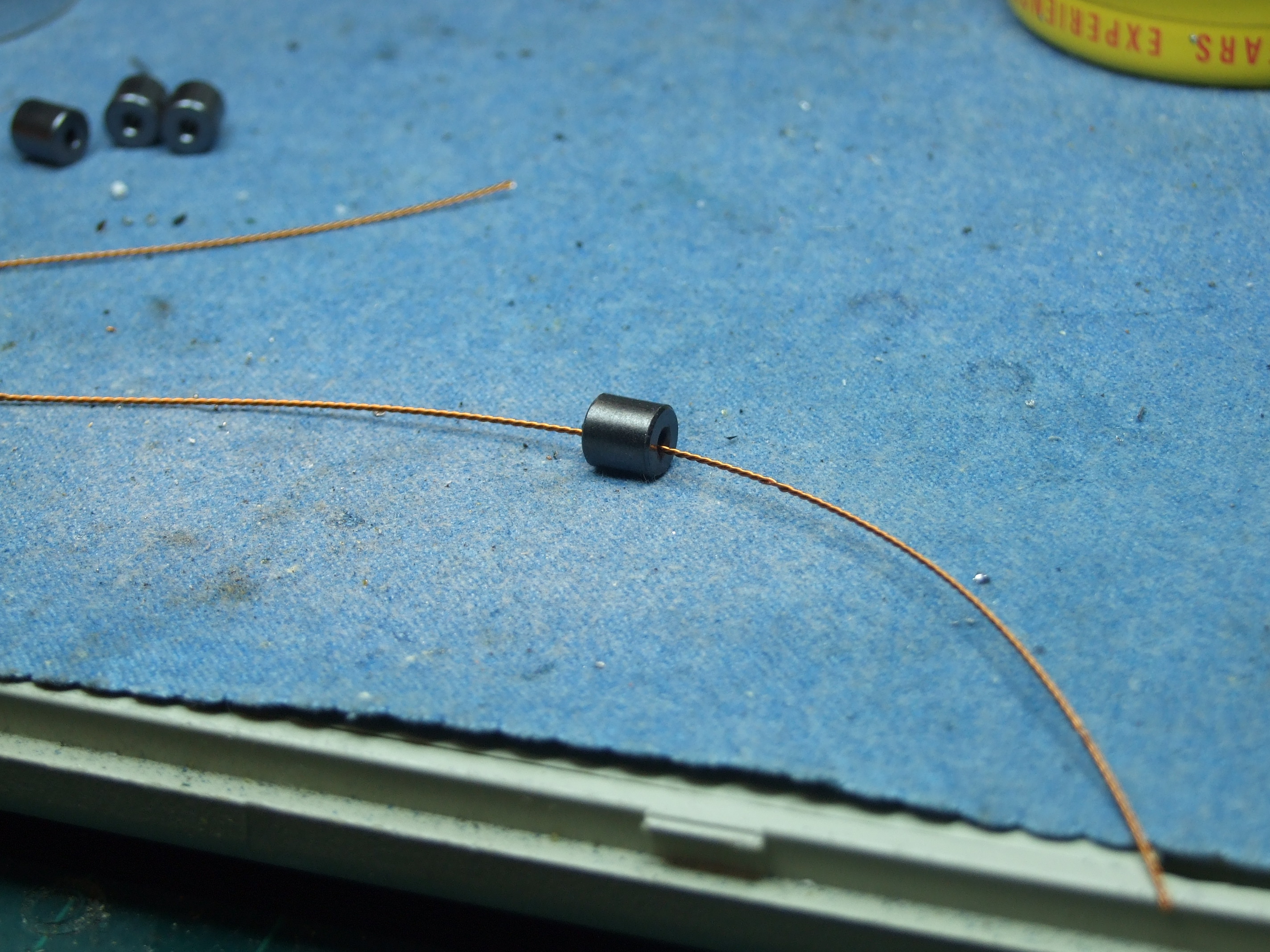
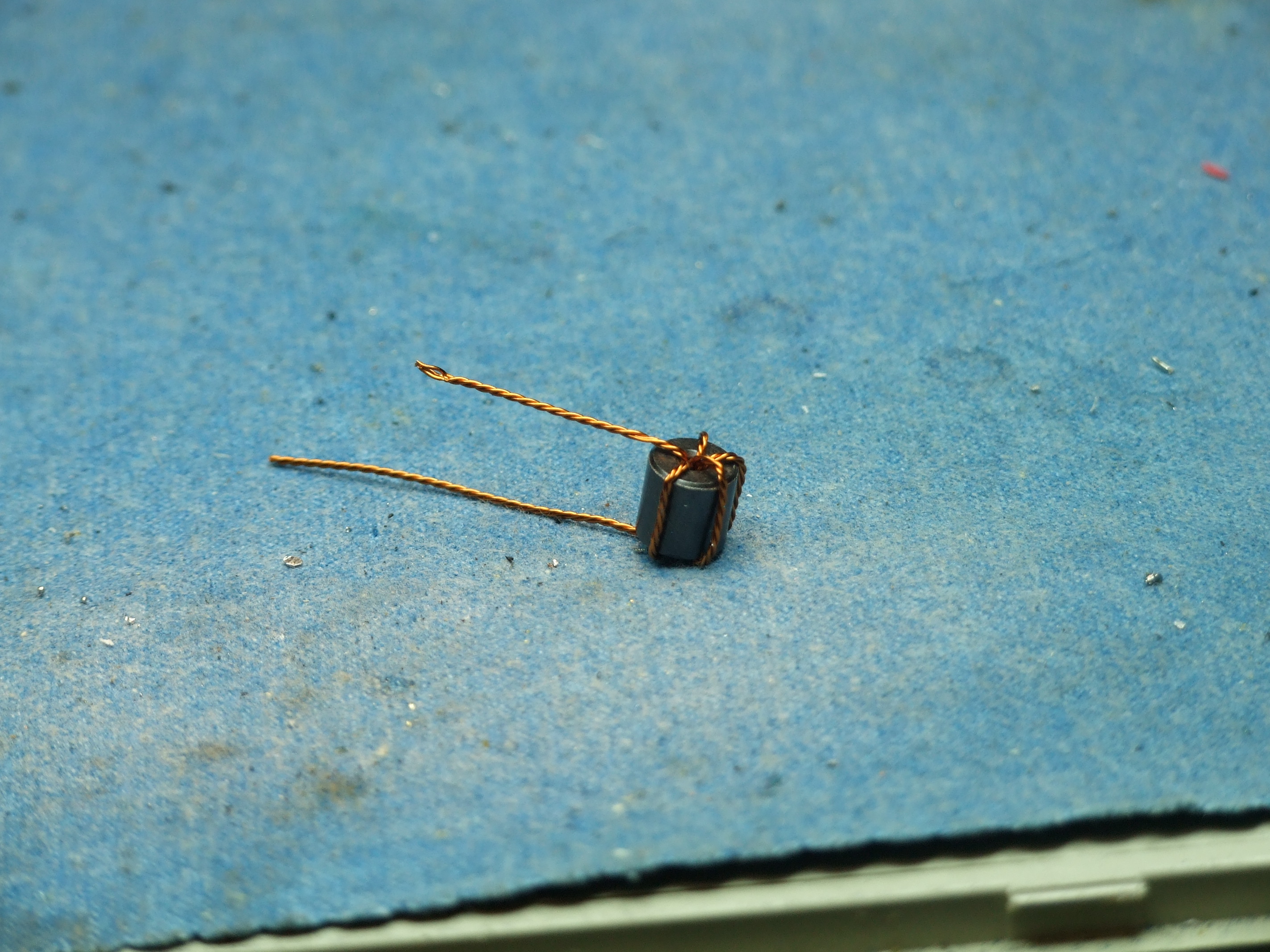
Passed very close to the coil, bent, without tight coupling to the core will become addicted.
Both ends of the coil, the core hole by re-passing Bending, wound three times state.
When repeating the above process all over
again, is that it looks like the following.
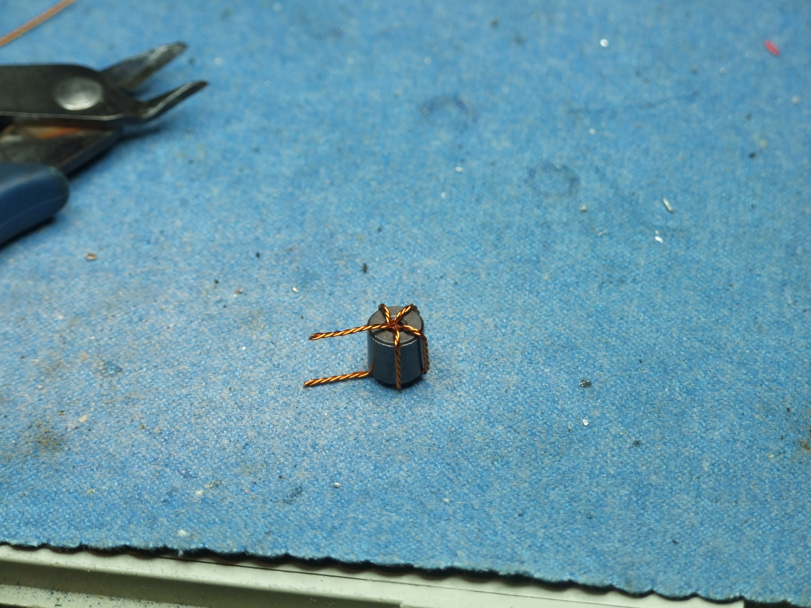
Like coiled coils, the coils are available in the core of the
entire surface to be distributed evenly, creating the appearance
will please. In this way, five times a complete matching
transformers are wound.
Cut to proper length,
Loosening of the coil twists, ensures that
each strand separation. Then, in the enamel surface of each
coil, by scraping with a knife or sandpaper to remove its.
At the end of the core, leaving about 2-3 mm is should take off.
Closely attached to the core position clear to the enamel, the
soldering process, each coil be short, so be sure to leave 2-3
mm job, please keep in mind.

This stripped the ends of the coil, as
measured by tester, electrically conductive coil in order to
relocate. Separated from each other by three strands of the
coil, are connected to each other is the process to find parts.
At this time, the different strands know of each other make sure
that insulation is required. If the coil is short-Peel, please
re-winding. Once you are this type, in order to give us a place
to solder on the PCB will be If you let.
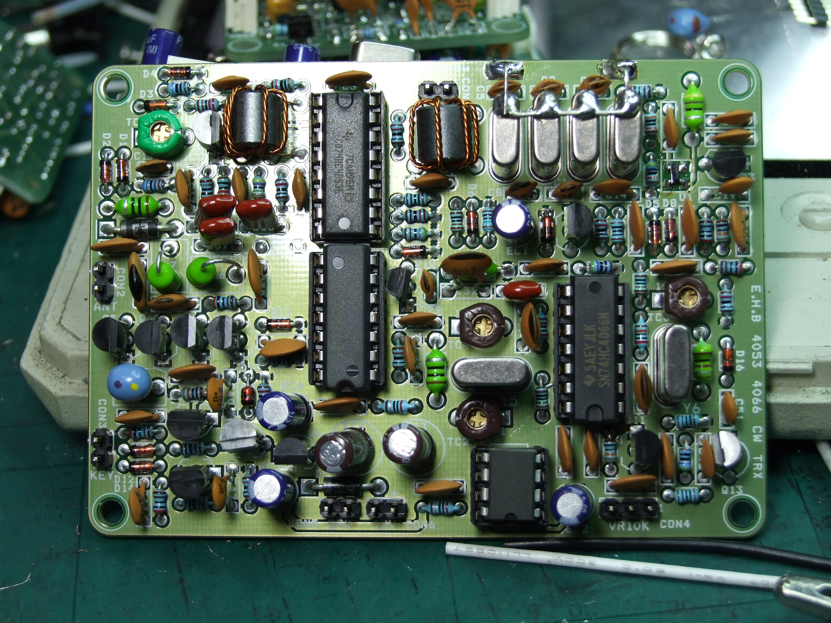
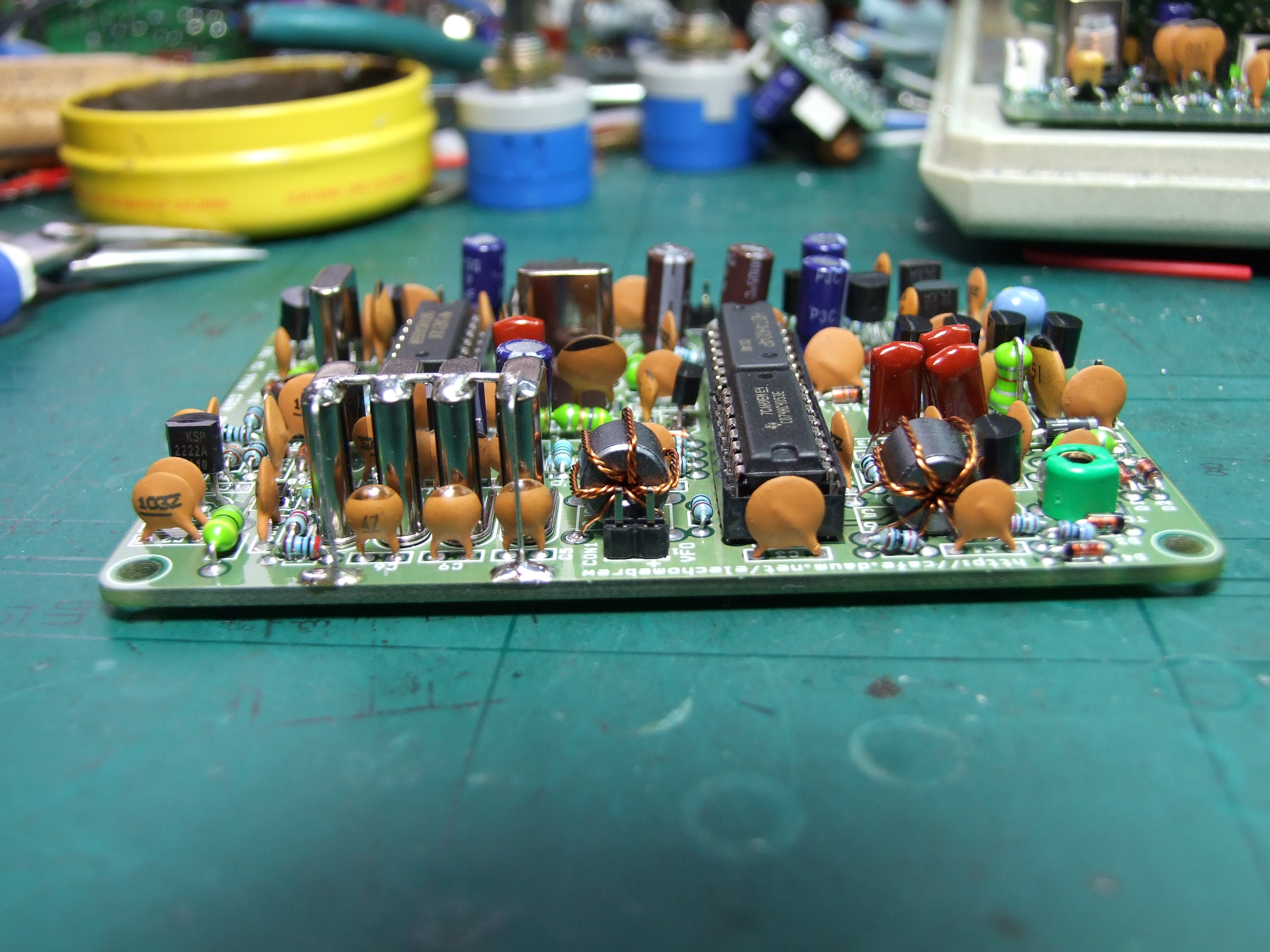
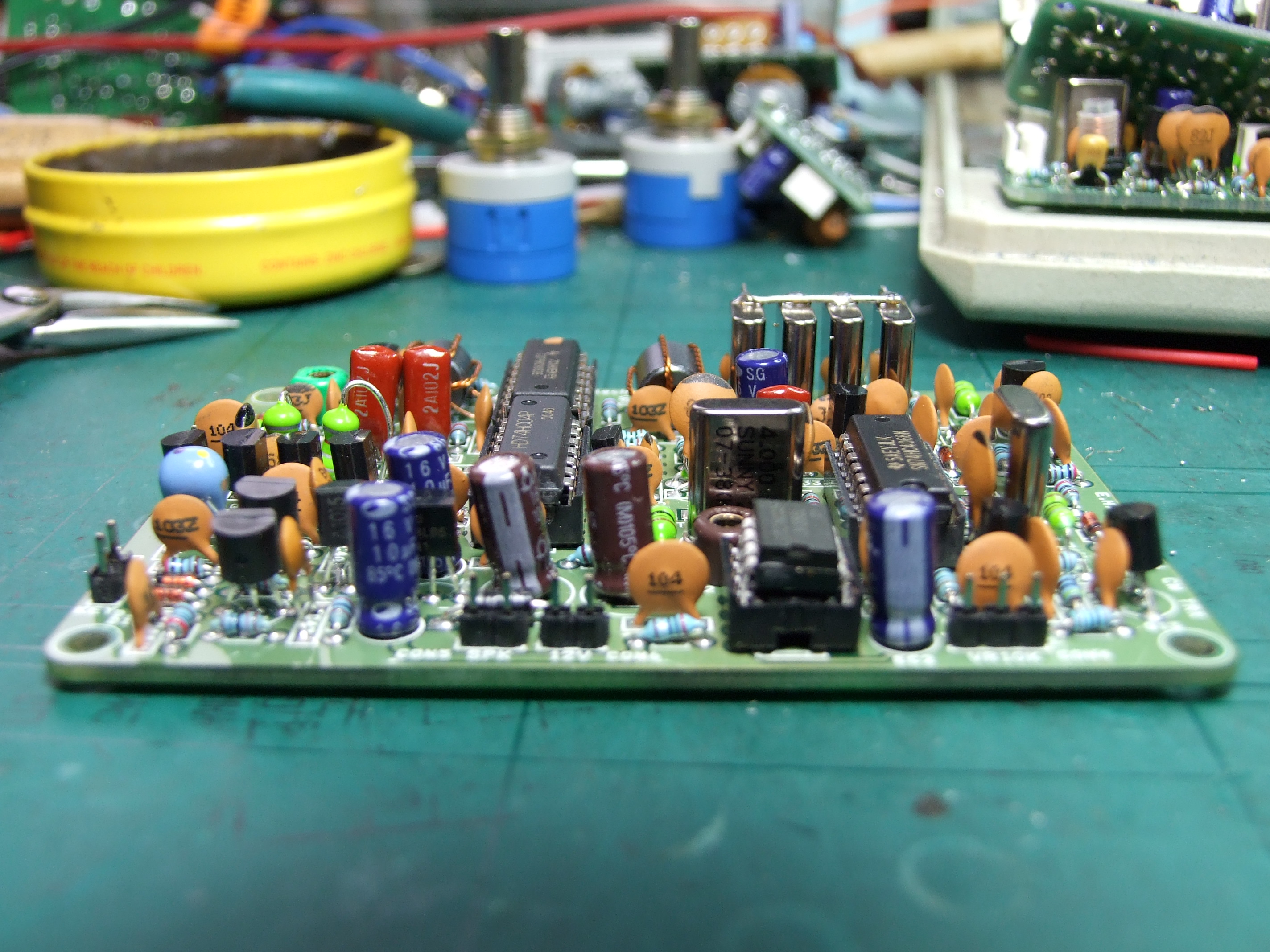
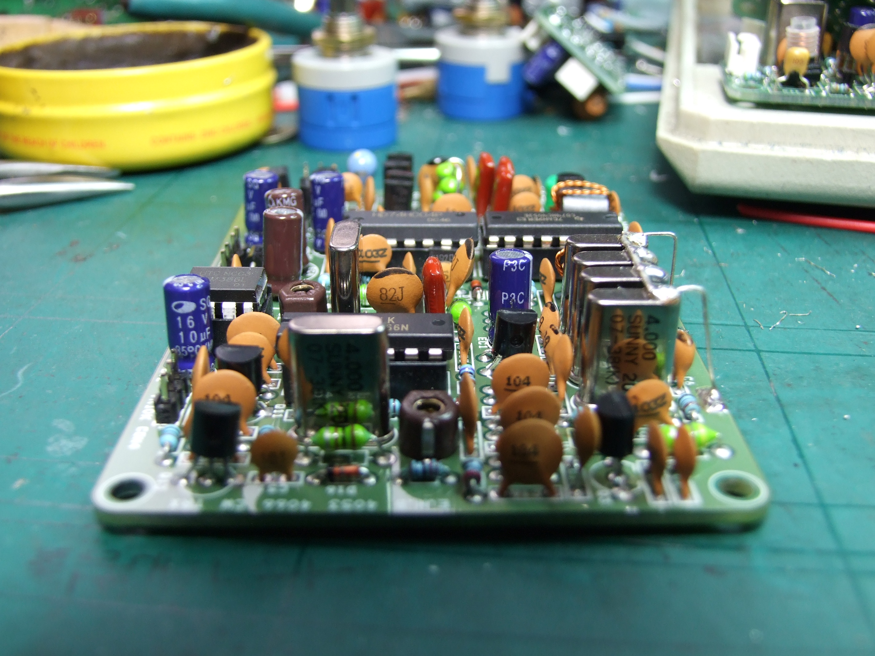
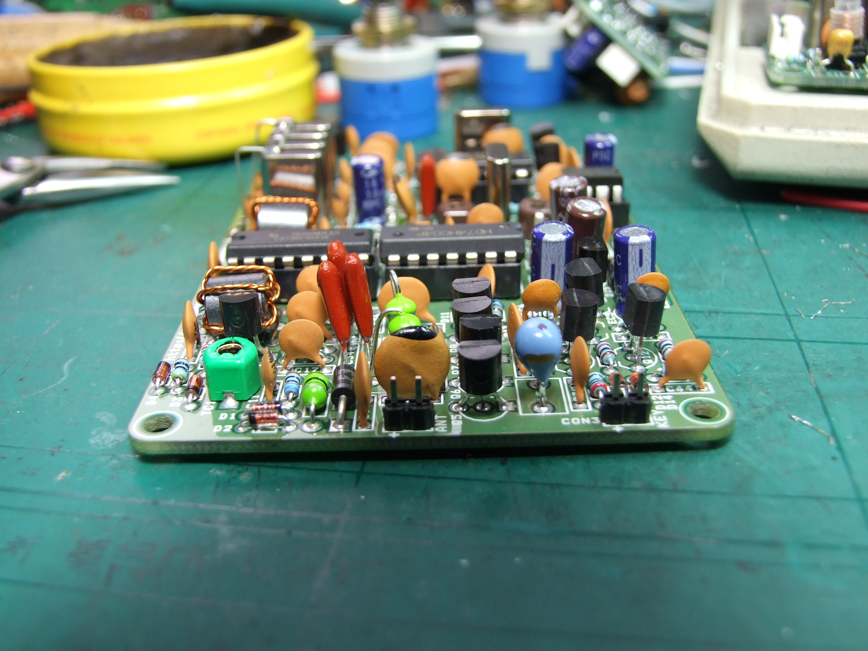
The appearance of the finished PCB is pictured below.
Respectively, are seen in terms of a four-look PCB. Click on the
photo, the size of the original can be viewed as a greatly
enlarged